本文介绍Intel CPU如何设置一个内存地址的memory type,也就是cache type.
MTRR
introduction
The MTRR mechanism allows up to 96 memory ranges to be defined in physical memory, and it defines a set of model-specific register (MSRs) for specifying the type of memory that is contained in each range.
Following a hardware reset, the P6 and more recent processor families disable all the fixed and viriable MTRRs, which in effect makse all of physical memory uncacheable.
Initialization software should then set the MTRRs to a specific, system-defined memory map. Typically, the BIOS (basic input/output system) software configures the MTRRs.
The operation system or executive is then free to modify the memory map using the normal page-level cacheability attributes.
In a multiprocessor system using a processor in the P6 family or a more recent family, each processor MUST use the identical MTRR memory map so that software will have a consistent view of memory.
Enumeration and configuraion
MTRRs are supported when CPUID.1_0:EDX.MTRR[12]. If MTRR bit is 1. then can use RDMSR to read the 64-bit read-only MSR IA32_MTRRcap:
IA32_MTRRCAP MSR
- bit 0-7: VCNT (variable range registers count), indicates the number of variable ranges implemented on the processor.
- bit 8: FIX (fixed range registers supported) flag, Fixed range MTRRs (IA32_MTRR_FIX64K_00000 through IA32_MTRR_FIX4K_0F8000) are supported when set; no fixed range registers are supported when clear.
- bit 10: WC (write combining) flag, The write-combining (WC) memory type is supported when set; the WC type is not supported when clear.
- bit 11: SMRR (system-management Range Register) flag, The system-management range register (SMRR) interface is supported when set.
IA32_MTRR_DEF_TYPE MSR
设置不被MTRRs覆盖的physical memory的default propertyies.
- bit 0-7: Indicates the default memory type used for those physical memory address ranges that do not have a memory type specified for them by an MTRR.
The legal values for this field are 0(UC), 1(WC), 4(WT), 5(WP), 6(WB). - bit 10: FE (fixed MTRRs enabled) flag, Fixed-range MTRRs are enabled when set; fixed-range MTRRs are disabled when clear. When the fixed-range MTRRs are enabled, they take priority over the variable-range MTRRs when overlaps in ranges occur.
If the fixed-range MTRRs are disabled, the variable-range MTRRs can still be uesd and can map the range ordinarily covered by the fixed-range MTRRs. - bit 11: E (MTRRs enabled) flag, MTRRs are enabled when set; all MTRRs are disabled when clear, and the UC memory type is applied to all of physical memory.
When this flag is set, the FE falg can disable the fixed-range MTRRs; when the flag is clear, the FE flag has no affect. When the E flag is set, the type specified in the default memory type field is used for areas of memory not already mapped by either a fixed or variable MTRR.
Fixed Range MTRRs
The fixed memory ranges are mapped with 11 fixed-range registers of 64 bits each. Each of these registers is divided into 8-bit fields that are used to specify the memory type for each of the sub-ranges the register controls:
Registers IA32_MTRR_FIX64K_00000 – Maps the 512-KByte address range from 0H to 7FFFFH. This range is divided into eight 64-KByte sub-ranges.即该64 bits的寄存器,每个字节(8 bits)表示一个64-KByte的sub-ranges的type.
Registers IA32_MTRR_FIX16K_80000 and IA32_MTRR_FIX16K_A0000 – Maps the two 128-KByte address ranges from 80000H to BFFFFH. This range is divided into sixteen 16-KByte sub-rangs, 8 ranges per register.
Registers IA32_MTRR_FIX4K_C0000 through IA32_MTRR_FIX4K_F8000 – Maps 8 32-KByte address ranges from C0000H to FFFFFH. This range is divided into 64 4-KByte sub-ranges, 8 ranges per register.
总结:
IA32_MTRR_FIX64K_00000每个字节(8bits)表示一个64KByte的范围
IA32_MTRR_FIX16K_80000 16
IA32_MTRR_FIX16K_A0000 16
IA32_MTRR_FIX4K_C0000 4
IA32_MTRR_FIX4K_C8000
IA32_MTRR_FIX4K_D0000
IA32_MTRR_FIX4K_D8000
IA32_MTRR_FIX4K_E0000
IA32_MTRR_FIX4K_E8000
IA32_MTRR_FIX4K_F0000
IA32_MTRR_FIX4K_F8000
Variable Range MTRRs
PAT - Page Attribute Table
The Page Attribute Table (PAT) extends the IA-32 architecture’s page-table format to allow memory types to be assigned to regions of physical memory based on linear address mappings.
The PAT extends the functions of the PCD and PWT bits in page tables to allow all five of the memory types that can be assigned with the MTRRs (plus one additional memory type) to also be assigned dynamically to pages of the linear address space.
The PAT was introduced to IA-32 architecture on the Pentium III processor. It is also available in the Pentium 4 and Intel Xeon processors.
Detecting Support for the PAT feature
CPUID.1_0:EDX.PAT[bit 16] -> Support PAT, and IA32_PAT msr.
Note that there is no separate flag or control bit in any of the control registers that enables the PAT.
The PAT is always enabled on all processors that support it, and the table lookup always occurs whenever paging is enabled, in all paging modes.
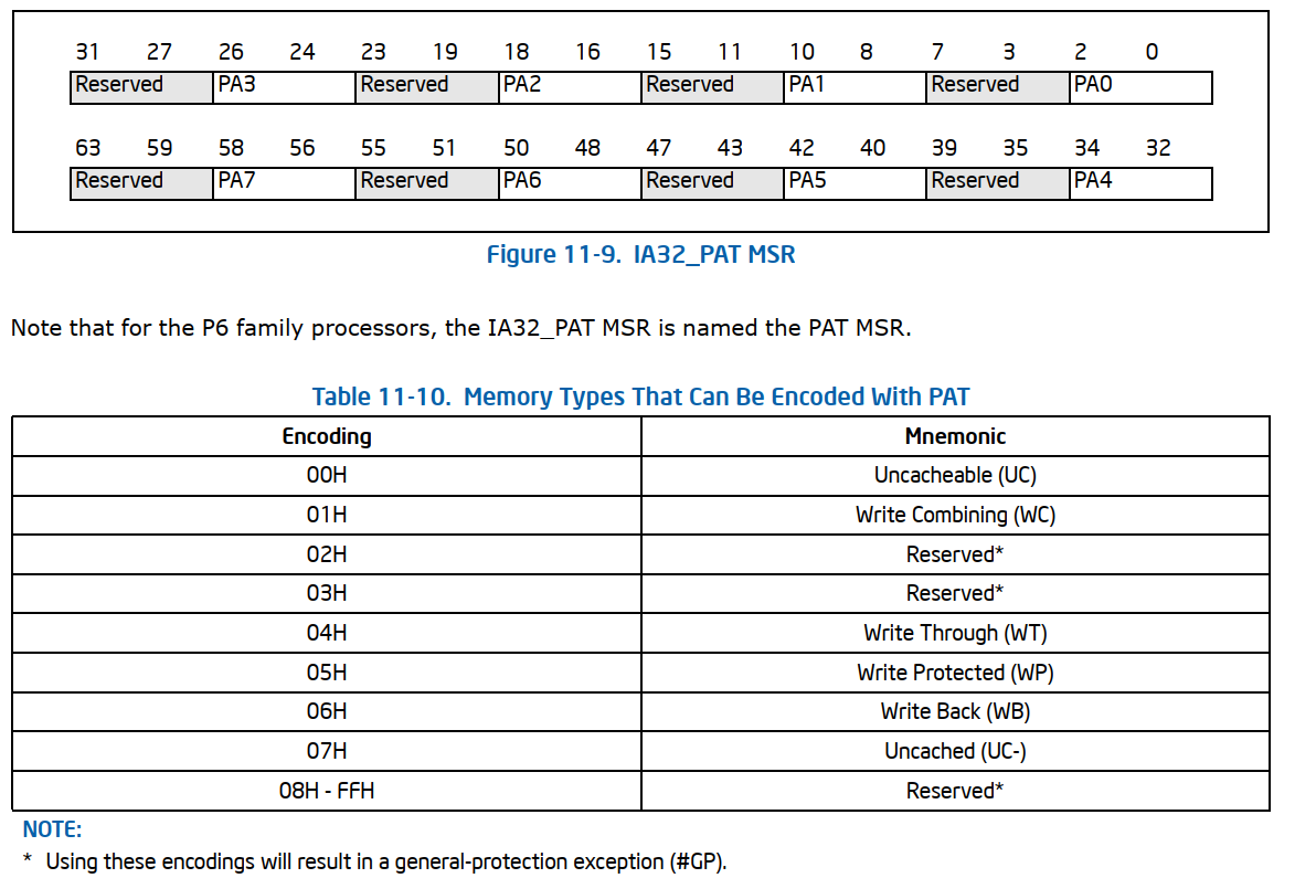
IA32_PAT msr
- Address 0x277H.
- The IA32_PAT MSR包含8个page attribute域:PA0 ~ PA7.每个域占一个字节,且每个域的低3位为有效位,可以指定一个memory type;高5个bits是reserved bits,必须为0。
- 这8个域可以被指定为任意一种memory type.

使用PAT为Page页设置memory type
用来指向一个page页的Page-table 或者 Page-directory的PAT、PCD、PWT三个bits连起来指定一个PAT entries(PA0 ~ PA7)。
The bit 7 in page-table entries that point to 4-KByte pages and bit 12 in paging-structure entries that point to larger pages.
The PCD and PWT bits are bit 4 and 3, in paging-structure entries that point to pages of any size.
配置PAT entries PA0 ~ PA7
下图为在power up或者reset之后,默认的PAT entries的配置。soft reset(INIT reset)不会改变该配置。
可以使用WRMSR来配置IA32_PAT msr从而配置不同的PAT entries(PA0 ~ PA7)。
#11.5 CACHE CONTROL
11.5.1 Cache Control Registers and Bits
- CR0.CD[30]:
- CR0.NW[29]:
- PCD and PWT flags in paging-structure entries: control the memory type used to access paging structures and pages.
- PCD and PWT flags in CR3: Control the memory type used to access the first paging structure of the current paging-structure hierarchy.
- G(global) flag in the page-directory and page-table entries:
- PGE(pagee global enable) flag in CR4:
- Memory type range registers (MTRRs)(从P6 family开始)
- Page Attribute Table(PAT) MSR (从Pentium III开始)
- Third-Level Cache Disable flag, IA32_MISC_ENABLE.[6] (只有Intel NetBurst微架构):允许单独地disable/enable L3 cache.
- KEN# and WB/WT# pins(Pentium processor):
- PCD and PWT pins(Pentium Porcessor):
11.5.2 Precedence of Cache Controls
Cache control flags 和MTRRs 一起层次地(hierarchically)限制caching。此处的层次我也不是很懂,具体表现如下:
- 如果CR0.CD[30] flag被置上(为1),那么caching是全局禁止的。
- 如果CR0.CD[30] flag被清掉(为0),那么page-level cache control flags and/or MTRRs 可以被用来限制caching:
具体地,如果这两者有冲突,禁止caching会有更好的优先级。也就是说:- 如果MTRR配置一个memory region为 uncacheable, 那么page-level caching control不能将该区域配置为enable caching.
- 反之,也成立。即如果page-level caching control指定一个page为uncacheable, MTRR的配置也能将该page变为cacheable.
- 如果write-back和write-through的caching policies同时指定到a page and a region of memroy.
the write-through policy占更高的优先级。
另外write-combining policy(只能通过MTRR或者PAT来指定)比write-through, write-back的优先级更高。
也就是write-combining > write-through > write-back - page level的memory type取决于是否enable了PAT.
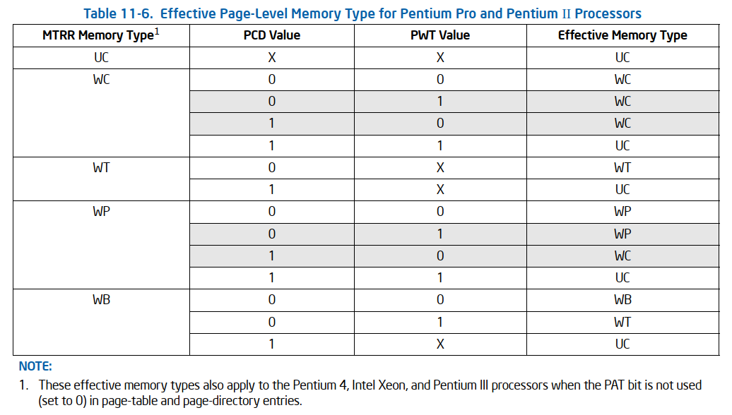
11.5.2.1 Pentium Pro and Pentium II processors的memory types
Pentium Pro and Pentium II处理器不支持PAT。
一个page页的有效memory type取决于MTRR和 决定该page的page-table/page-directory的PCD和PWT bits。
当normal caching is in effect( CR0.CD[30] and CR0.NW[29]都为0)时,the effective memory type由以下的规则决定:
- 如果page的PCD和PWT为都0,那么有效的memory type由MTRR决定。
- 如果page的PCD为1,那么有效的memory type为UC.
- 如果page的PCD为0,并且PWT为1。如果MTRR为WB, 那么有效的memory type是WT; 其他情况下就为MTRR的type.
- 当PCD和PWT为相反的值得时候, 那么MTRR为WP, WC时,最有的有效memory type是model-specific的(我们应该避免);当MTRR为WB,WT,UC时,有效的memory type是结构统一的。
具体见下图。
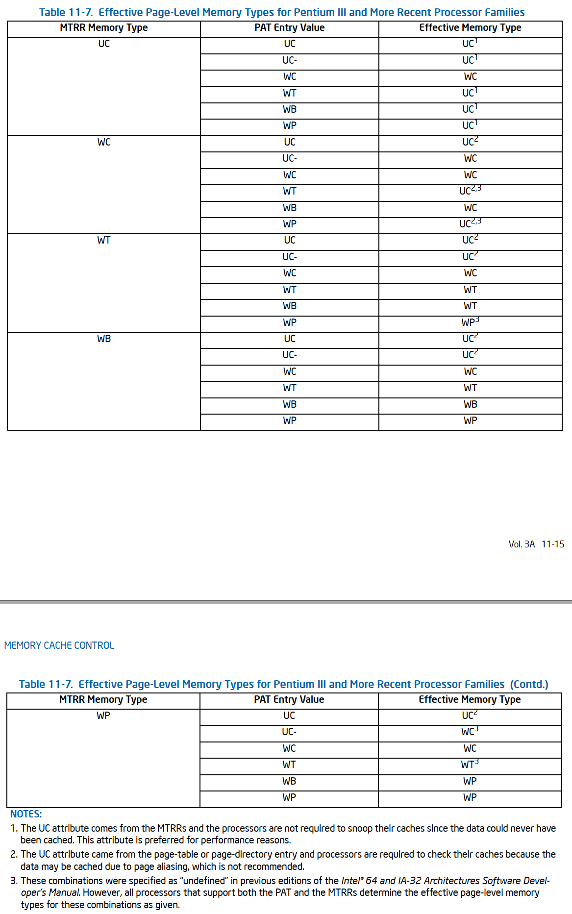
11.5.2.2 Pentium III and More Recent Processor Families
The Intel Core 2 Duo, Intel Atom, Intel Core Duo, Intel Core Solo, Pentium M, Pentium 4, Intel Xeon, and Pentium III processors使用PAT来选择有效的page-level memory types.
此时PAT的memory type由[PAT,PCD,PWT]bits决定的PAT entry决定。
如果normal caching is in effect( CR0.CD[30] and CR0.NW[29]都为0)时,the effective memory type由以下的规则决定:
11.5.2.3
如果两个相邻的page页为不同的memory type,当内存写操作跨这2个memory pages的时候, 那么这个操作数可能会别写2次。
如果是向实际的内存写,那么上述的两次写不会有问题;如果写的是memory-mapped device page,那么这个设备可能会发生故障(malfunction)

